Safety can be sold…
If you want to!!!
We strive for you safety. We would like to explain to you what we are doing about it:
In the not so distant past a theory was introduced which said that since safety was connected with extra costs it would be impossible to sell for sailplanes and motor sailplanes.
We would like to make it clear that we see this differently. In our designs we have for a long time taken care to consider the possibility of accidents and the elimination of sources of danger. This thinking has been incorporated into our designs without considering unsafe or less expensive alternatives.
Cockpitstruktur
The report from the TÜV Rheinland on “ Occupant safety during accidents in sailplanes and motor sailplanes” (Sperber, M.: TÜV Rheinland, Köln, March 1998) was especially responsible for the discussion concerning the degree to which the newly acquired knowledge had been put into practice. It states:
“The cockpit area from the fuselage nose to the front wing torsion fittings is basically divided into two zones.
The fuselage nose should be as long as possible and should be designed as a crushable zone or energy absorption element. The life saving area extends from the foot former to behind the head rest. This area must be resistant to buckling and able to transmit exterior forces around the pilot.
The area behind the actual life saving area must be designed stiff enough so that the stress loads arriving from the front are transferred to the rear fuselage structure or wings.”
These observations can already be recognized in Rudolf Kaiser’s designs, for example with the Ka 6. To be sure, the crash safety of a wooden sailplane can never be compared to that of a modern composite structure.
However, he recognized that it was necessary to connect the canopy area with the rear fuselage structure because of the former’s vulnerability to buckling. The canopy frame does not end at the back of the canopy but is extended by means of stringers past three fuselage bulkheads to the rear fuselage. 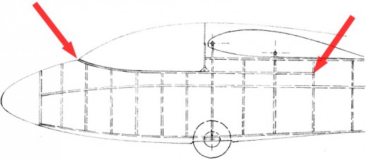
According to TÜV research, a massive crossbeam under the pilot’s knees should be employed to prevent buckling of the cockpit. For this reason the ASW 15 and 17 seatpans were integrally bonded to the front of the fuselage. When this was no longer possible with the ASW 19 fuselage an appropriately dimensioned, elevated control bulkhead with large bonding surfaces was incorporated into the design. Three stringers on each side, one for the canopy frame, one for the seat pan supports and one for the safety belt attachments additionally stiffened the front fuselage.
The cockpits of the ASW 19/20 were already designed with a soft nose which would fail under relatively light impact forces while the cockpit stayed intact. In the case of accidents with higher impact energies, the cockpit sidewalls would break in three places, but always out rather than in. Gerhard Waibel designed the life preserving cell of the ASW 24 with an additional 20% in strength. The canopy frame was built as buckle resistant as possible. It was not only built to carry bending loads with a high moment of inertia but is also straight and does not follow the fuselage contour. The TÜV Rheinland recommends avoiding structural bonding of the canopy frame. However, we have found a method to do this safely and accident investigations to date agree with us. The upper part of the canopy frame is folded inward on the fuselage side in order to provide a wider support surface for the hands. The canopy shape and corresponding fuselage cut-outs are rounded in order to ensure the transfer of forces to the mid and rear fuselage sections and to avoid high stress points.
 |
Minimal cause, great effect: it’s easy to imagine that a rod under pressure along its length can take greater loads when it’s straight. Obviously, a pre-curved rod can take lower bending moments. That is why at Schleicher all single seaters, ever since the ASW 24, have straight canopy frames on the inside. |
The Carbon-Aramid material combination, first used for aviation purposes by Akaflieg Stuttgart in their fs 31, was utilized for the ASH 25 right from the start. While the carbon fibres take care of the high specific strength and stiffness requirements, the equally light but tough Aramid prevents a sudden splintering of the structure during overloads.
Impact tests by the Aachen University of Applied Sciences (FH Aachen)
During the development of the ASW 27 FH Aachen conducted ground impact tests for a parachute based rescue system for sailplanes (“Verbesserung der Insassensicherheit bei Segelflugzeugen und Motorseglern durch integrierte Rettungssysteme”; Röger, W.; Stabenau, P.; Conradi, M; FH Aachen, April 1994 and “Insassensicherheit bei Luftfahrtgerät”, Röger, W.; Conradi, M.; Ohnimus, T.; FH Aachen, December 1996 ). As a result it was possible to test the cockpit crash characteristics of the design.
FH Aachen was especially interested in finding the maximum permissible sinking speed of a parachute based rescue system, particularly since a relatively small increase in permissible impact velocities would result in noticeably smaller parachutes and significant weight savings. Consequently, the most important test parameters were the acceleration forces experienced by the test “dummy”.The acceleration forces mearured in the ASW 27 fuselage were under the maximum allowable limits established by the automobile industry. For us who – until now – do not offer a total rescue parachute system, the behaviour of the cockpit structure was more interesting.
Four of the 20 droptests were carried out with test fuselage 2 (the eventual ASW 27). For these tests the vertical angle was always -45°, which means that the nose always impacts the ground first and the force of the impact tries to fold up the cockpit.
| Test | Sinking speed | Weight | Notes |
| 5 | 6 m/s | 356 kg | onto pasture land |
| 7 | 8 m/s | 355 kg | onto pasture land |
| 9 | 6 m/s | 356 kg | onto asphalt |
| 12 | 8 m/s | 527 kg | onto pasture land, maximum weight |
The kinetic energy for a sinking speed of 8 m/s is 78% larger than that for 6 m/s. Consequently, test 7 is more interesting than test 5. The documentation for test 7 shows that 90 milliseconds (ms) after impact the cockpit sidewalls buckle out in the area of the instrumentpanel but that 100 ms later they spring back. This means that the cockpit area was deformed but remained as a protecting shell right to the end. Tests with other (non-series) fuselages (one specially strengthened, the other conventional) with the same configuration showed that the former broke its canopy frame 85 ms and the latter 30 ms after impact, followed by folding up of the cockpits. In the case of the conventional cockpit the dummy impacted the ground with his bottom 110 ms after impact.
Test 9 was used to compare the difference between impact on solid ground versus soft, impressionable ground. Impact on asphalt results in a 70 cm long deformation of the nose at an angle of 45° to the longitudinal axis. This is in the area of the specially constructed energy absorbing crumple zone. The fuselage then rotates tail down and lifts off again briefly until the tail skid and main fuselage impact again. The fuselage shell is cracked in the area of the cockpit but not broken.
Test 12 is the only test at an aircraft weight of over 357 kg, namely 527 kg, which is 2 kg over the maximum ASW 27 take-off weight and at least 47% higher than for all the other tests. Because of the high kinetic energy the nose crumple zone is completely pushed in, the cockpit walls fold out sideways and the fuselage impacts a second time. Despite the already destroyed canopy frame, the cockpit in the vicinity of the seat pan ensures that the loads remain below maximum allowable limits.
As a result of these tests the layup components were changed again (ASW 27 TM1). Instead of straight carbon and polyester fabrics the ASW 27 and ASW 28 front fuselages are now built with hybrid carbon-polyester fabrics (similar to Formula 1 racing cars).
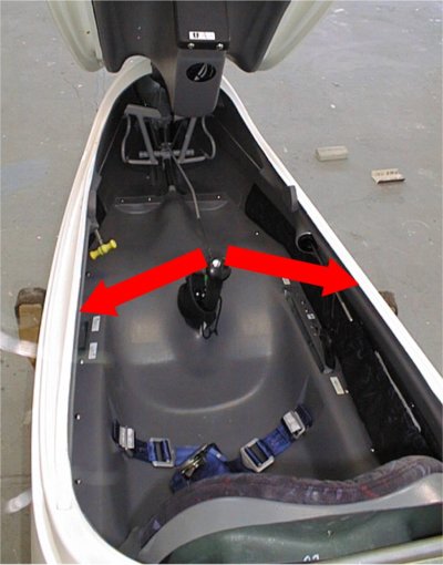
We recommend making a simple test which can provide a good indication of the cockpit stiffness. Kneel beside the cockpit with the canopy open and try to push the left and right cockpit walls apart. The easier that is, the more likely it is that the cockpit will break apart in the pilot’s seating area in the case of an accident. However, in the case of an actual accident the load forces would likely be different and this test provides no information about dynamic behaviour or load factors.
Also: the tests showed again how important it is to have tight safety belts, particularly the hip belts. For one thing, it’s important to avoid having the hip belts pulled up by the shoulder belts (the shoulder belts get more play) and the pilot thereby slips under the hip belts (submarining). As well, during the impact tests loading peaks always occurred when the dummy lifted off from the seat pan, the fuselage bounced off the ground and both collided again. Not to mention the possibility of serious head injuries with loose shoulder belts.
Additional aspects of accident safety: Landing gear, Propeller tower, Stall warning
The landing gears of our aircraft possess long suspension travel. This can help to avoid serious spinal injuries during heavy impacts. In the ASW 27 and 28 the landing gear struts have purpose built, pre-determined breaking points since it’s perferable to have a strut break rather than your spine. This issue had to be thoroughly discussed first with the licensing authorities since no official documentation exist for the intentional failure of a landing gear.
Normally there is a safety cable between the propeller hub and the back of the motor box of motorized sailplanes. This is to prevent the extended propeller tower from folding forward over the cockpit in case of an accident. But who can guarantee that in such a situation the rear fuselage is still intact and can actually restrain the propeller tower from moving forward? Martin Heide did not want to rely on that during the design of the engine system for the ASH 25 M and ASH 26 E. Consequently, the propeller tower itself and its mounts have been designed to withstand crash loads. In addition, the tower and the engine pivot around the same mounting point. In case of significant deceleration the engine would pull the propeller tower to the rear.
We don’t very much believe in electronic stall warnings. We are used to the stall warning provided by the shaking of the tailplane which directly depends on the angle of attack and thus on the achieved lift coefficient. That is the critical parameter which must be controlled. Other procedures which depend on the measuring the airspeed and load factors will fail if the wing loading is not correctly taken into account. Then such a stall warning device is more dangerous than not having one at all. However, if such a system is absolutely necessary, some manufacturers of glide computers offer it as an option (for example Cambridge). Some gliding computers also offer landing gear warnings and unlocked dive brake warnings.